MEaSUREs Greenland Monthly Image Mosaics from MODIS, Version 1
Data set id:
NSIDC-0724
DOI: 10.5067/6L166FFRPCPP
This is the most recent version of these data.
Version Summary
Version Summary
Initial release
Overview
This data set, part of the NASA Making Earth System Data Records for Use in Research Environments (MEaSUREs) program, consists of monthly image mosaics of the Greenland coastline and ice sheet periphery constructed from composited MODIS imagery.
See Greenland Ice Mapping Project (GIMP) for related data.
Parameter(s):
ICE EDGESSURFACE MORPHOLOGY
Platform(s):
Aqua, Terra
Sensor(s):
MODIS
Data Format(s):
GeoTIFF
Temporal Coverage:
1 March 2008 to 30 September 2016
Temporal Resolution:
- 1 month
Spatial Resolution:
- 100 m
- 500 m
- 100 m
- 500 m
Spatial Reference System(s):
WGS 84 / NSIDC Sea Ice Polar Stereographic North
EPSG:3413
Spatial Coverage:
N:
85
S:
57
E:
11
W:
-109
Blue outlined yellow areas on the map below indicate the spatial coverage for this data set.
Data Access & Tools
A free NASA Earthdata Login account is required to access these data. Learn More
Sample Data Image
Image

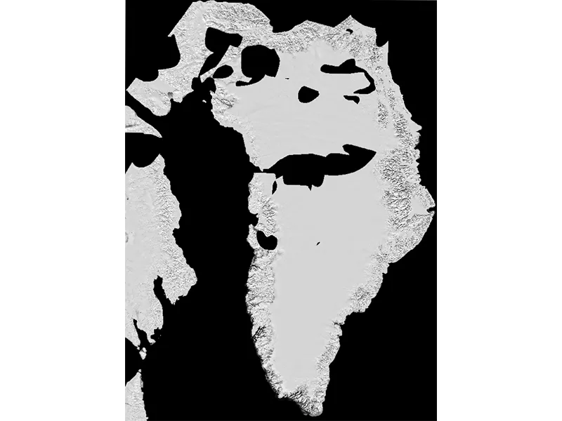
This map is a monthly image mosaic of Greenland, which shows the surface morphology, and the glacier ice edge at the calving fronts in fjords. The mosaic is derived from high-pass filtered MODIS Band 1 (red light) images. Credit: NASA MEaSUREs GrIMP Data: NASA MODIS
Documentation
Help Articles
How to Articles
Many NSIDC DAAC data sets can be accessed using the NSIDC DAAC's Data Access Tool. This tool provides the ability to search and filter data with spatial and temporal constraints using a map-based interface.Users have the option to
Below the image in this article, you will find sample code in IDL, MATLAB, and Python to read in a GeoTIFF file, extract the metadata, and create an image.
The code has been tested with the following data products:
We recommend using the Geospatial Data Abstraction Library (GDAL) to convert GeoTIFF files into a different format.
We recommend using the Geospatial Data Abstraction Library (GDAL) or a GIS to reproject geoTIFF files.
All data from the NASA National Snow and Ice Data Center Distributed Active Archive Center (NSIDC DAAC) can be accessed directly from our HTTPS file system, using wget or curl. Basic command line instructions are provided in the article below.